
Q&A: Making a UniFi and Cisco Network
Originally Posted: May 9th, 2021
Q&A: Making a UniFi and Cisco Network
Question:
I have a UDM-Pro and a Cisco layer 3 switch, with two local networks: 192.168.10.0 and 10.1.100.0. How can I configure the UDM-Pro so that my devices on one local network can communicate to the other local network?
Answer:
The answer depends on where your routing is happening. Cisco layer 3 switches can act as L3 routers or L2 switches, and individual ports can be L3 (routed, assigned an IP address) or L2 (switchports, assigned a VLAN). If you want to understand VLANs and network layers better, refer to my Networking 101: VLANs and Network Layers post.
I’m going to assume VLAN 10 = 192.168.10.0/24 and VLAN 100 = 10.1.100.0/24, but that’s up to you.
UniFi and Cisco (or any other network vendor) can work together. Hurray for open networking standards!
If the Cisco L3 switch is routing:
Enable routing with the “IP routing” global configuration command on the Cisco switch.
You can make two separate physical L3 routed ports on the Cisco switch, or make Switch Virtual Interfaces (SVIs) for the two networks.
Create the two VLANs on the Cisco switch, if needed. From global configuration mode:
vlan 10
   name Guest
vlan 100
   name LAN
If you want multiple networks to go across a single cable, you’ll want to use SVIs and a router-on-a-stick style network.
Make the L3 VLAN interfaces (SVIs) on the Cisco switch. From global configuration mode:
interface vlan 10
   description Guest
   ip address 192.168.10.1 255.255.255.0

interface vlan 100
   description LAN
   IP address 10.1.100.1 255.255.255.0
Create the networks as VLAN only networks in UniFi, and match up the VLAN numbers.
Make the connection from the UDM-Pro to the Cisco switch a L2 trunk on both sides. UniFi does this automatically. On the Cisco switch, that would look something like:
interface GigabitEthernet1/0/1
   switchport mode trunk
   switchport trunk encapsulation dot1q
   switchport trunk native vlan 10
   switchport trunk allowed vlan 10,100
The native VLAN is the network that is used when there are no VLAN tags applied to the frame, and it’s what a normal client device will be able to access if plugged in. I chose to make that the “Guest” network, but that’s another thing that will change based on how you’re building your network.
The allowed VLAN line specifies which tagged VLANs are allowed on the trunk. When adding to that list, make sure you use the “switchport trunk allowed vlan add xxx” command, otherwise you’ll overwrite the current list of allowed VLANs.
Assign other ports and your Wi-Fi networks into VLANs 10 and 100 as needed.
Control access to the networks with ACLs assigned to the Cisco SVIs or routed interfaces.
The Cisco Catalyst 9300 is an example of a Cisco switch with L3 routing features.
If UniFi is Routing:
Disable routing on the Cisco device with the “no IP routing” global configuration command.
Create the VLANs on the Cisco device as shown above, if needed.
Create the networks in UniFi as corporate or guest networks, and match up the VLAN numbers.
Make the link to the the UDM-Pro a L2 trunk port as shown above.
In UniFi, all ports are trunk ports by default. You can customize them individually, or by using UniFi switch port profiles.

An example of a UniFi switch port profile. Here, we’re making an access port for devices that only need access to the Main LAN network, VLAN 100.
Assign other ports and Wi-Fi networks into VLAN 10 and 100, as needed.
Control access to the networks and communication between them with firewall rules on the UDM-Pro.
For UniFi firewall rules, things like DNS and DHCP are handled automatically. You can control some of those auto-rules by picking the network type. If you make two “corporate" networks in UniFi, they’re going to be able to talk to each other by default. If one of them is made into a guest network, you’ll need to manually allow the types of traffic you want to allow with firewall rules.
Have a question? Leave a comment or contact me and I’ll add it to this post.

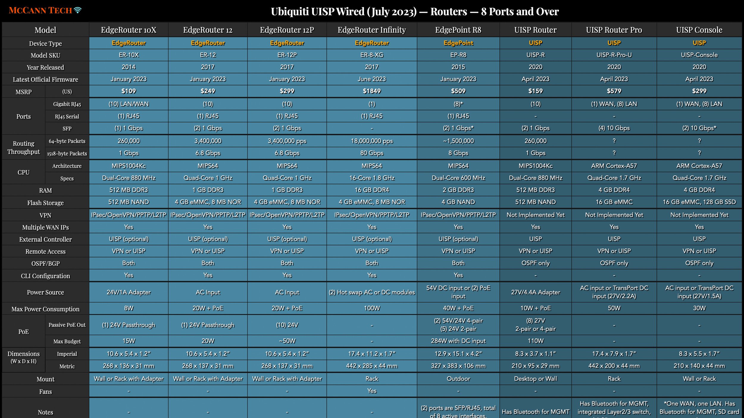


All my charts for comparing Ubiquiti’s models of UniFi Gateways, Consoles, Wireless Access Points, and Switches. Last updated in December 2024 for the Enterprise Fortress Gateway, UXG-Enterprise, Enterprise Campus switches, and E7 Enterprise Wi-Fi 7 access points.